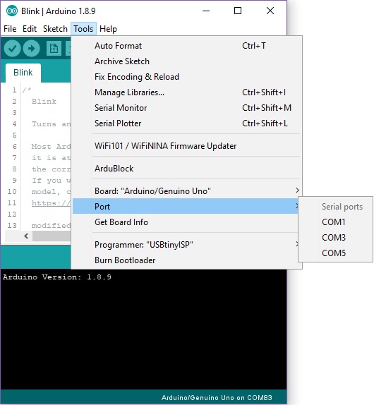
Arduino Drivers For Mac Arduino is one of the most popular micro-controller boards available in the market today. The ease of use and open-source design means that it has a huge community that can. We’ve done the hard work of figuring out the NodeMCU drivers and NodeMCU Arduino IDE setup for you. Read on for the two steps that have to be done only once. More helpful info at the end, too. Installing NodeMCU drivers for USB. This part of the instructions are written for Windows. They’re very similar for OSX and Linux. Neither is working for me. Not the given driver in Version 1.3 or 1.4 nor the default driver of Mojave. I also tried the new driver from mac-usb-serial.com. Also not working. My workaround: i use an external programmer USBtinyISP. That works like a charm.
- July 8, 2019
0
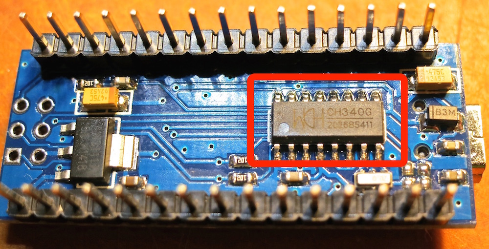
Clone Arduino & driver chip CH340, CH340G, CH341
Category : RESOURCES
The CH340/CH341 chip is used by a number of Arduino compatible cards to provide USB connectivity.
Many operating systems do not recognize these chip natively because they lack the drivers and consequently we have an error due to lack of drivers.
The lack of this driver does not allow you to communicate with the hardware platforms and to use the Arduino development software.
No panic, driver installation is very easy!
The driver must be downloaded from the official (Chinese) website.
Once the unzip of the package has been executed, it is possible to proceed with the update of the driver for the device CH340/CH341 and equivalent (download driver only for your OS):
Mac Arduino Usb Driver Free
WINDOWS 32/64bit (version: 3.4 – 2016/09/27)
Drivers in the Windows OS are missing, you need to download and install them.
LINUX 32/64bit (version: 1.5 – 2018/03/18)
The drivers are integrated into different Linux distributions. If the device is not recognized, download the Linux CH340/CH341 driver.
MAC OS 32/64bit (version: 1.5 – 2018/07/05)
This driver is for MacOS Sierra/High Sierra. Do not install the drivers for the Mojave, because it seems that the latest versions are equipped with the built CH340/CH341 support.
Installation
• Unplug any CH34* devices.
• Unload the old drivers if running:
• sudo kext unload /Library/Extensions/usbserial.kext
• sudo kext unload /System/Library/Extensions/usb.kext
• Remove the old driver by issuing one of the following commands (depending on your installation):
• sudo rm -rf /System/Library/Extensions/usb.kext
• sudo rm -rf /Library/Extensions/usbserial.kext
• Double-click on the CH34x_Install_V1.3.pkg file and install (no need to reboot)
• Instead of rebooting, you can force quit Installer after it completes.
• Load the new driver:
• sudo kextload /Library/Extensions/usbserial.kext
• Plug in your device. It should now be listed under the /dev directory. Examples:
• /dev/cu.wchusbserial1410
• /dev/cu.wchusbserial1420
ANDROID (version: 1.5 – 2018/03/18)
Enjoy!
In this project, I will talk about ATtiny85, what are the tools required for Getting Started with ATtiny85 board, installing drivers for Windows OS and finally how to program ATtiny85 Microcontroller using Arduino IDE.
A Brief Note on ATtiny85
The ATtiny85 Microcontroller is possibly the smallest Microcontrollers available today. It is an 8-bit Microcontroller based on the AVR RISC Architecture. Physically, it needs only 8-pins for complete operation (although some packages like QFN16 use 16-pins just for packaging).
There are three variants of ATtiny85: ATtiny25, ATtiny45 and ATtiny85. The main difference between these three ICs is the amount of memory each device has (Flash, EEPROM and RAM).
ATtiny85 Microcontroller, the target device of this project has 8KB of In-system programmable Flash, 512B of EEPROM and 256B of SRAM.
Pin Diagram of ATtiny85
As mentioned earlier, ATtiny85 is an 8-pin Microcontroller and the most common IC package for ATtiny85 is the 8-pin SOIC. The following image shows the Pin Diagram of an 8-pin SOIC ATtiny85.
From the above pin diagram, you can observe that except for VCC and GND, rest of the 6-pins of ATtiny85 are multiplexed with multiple functionalities.
Pin Description
VCC: It is the supply voltage pin. For ATtiny85 running at a speed of 10-20MHz, the supply voltage should be in the range of 2.7V – 5.5V.
GND: Ground Pin
PORTB (PB0 – PB5): The rest of the 6-pins in ATtiny85 are Port B Pin. Port B is a 6-bit I/O Port. All the 6 port B have multiplexed operations with each pin capable of handling 3 or more operations.
RESET: It is multiplexed with PB5. It is an active LOW pin.
The following image shows the list of alternative functions on the PORTB pins.
ATtiny85 Board
Several manufacturers started developing tiny development boards with ATtiny85 as the main controller. One such board is shown in the image below.
As you can see, apart from the ATtiny85 Microcontroller IC, there are a few other components on the board like a 5V Regulator, headers for I/O pins, few passive components and a MicroUSB port for programming and power supply.
Getting Started with ATtiny85 Board
Now that we have seen a little bit about ATtiny85 Microcontroller and its development board, lets dig into the aspects of how to use this board, what are the necessary tools (like Drivers) required and also how to program the ATtiny85 Microcontroller.
Arduino Usb Driver Mac Download
Let me start with programming ATtiny85. There are couple of ways you can program your ATtiny85 but I have chosen the easiest of all: using Arduino IDE to program ATtiny85. For this, you need to make some changes to the Arduino IDE.
Next important thing is the drivers. USB Drivers for ATtiny85 Board are very important as the driver is responsible for enabling the Arduino IDE to program the ATtiny85.
Detailed Video
Before looking at the steps involved for getting started with ATtiny85 board, take a look at the following video, which basically explains the same.
Setting up Arduino IDE
The first step is to setup Arduino IDE for programming ATtiny85. Open your Arduino IDE and go to File à Preferences. In the tab that says “Additional Boards Manager URLs:”, copy and paste the following link and click on ok.
This is similar to what you might have done for ESP8266.
Now, go to Tools → Board: → Board Manager… and search for “Digistump AVR Boards”. Select the same and click on install. If the installation is successful, you can see the board in Tools → Board: option. We will come back to this later.

Installing Drivers
Next step is to install the necessary USB drivers for the ATtiny85 board. I will specify how to install drivers for Windows system. Go to the following link and download the “Digistump.Drivers.zip” file. Extract the contents of the zip file and double click on “DPinst64” application to install the drivers.
NOTE: If your system is a 32-bit system, select “DPinst” application.
Once the drivers are successfully installed, you can plug in your ATtiny85 board to the computer using an USB cable. To check if the device is detected or not, go to Device Manager on your Windows and your device will be listed under “libusb-win32 devices” as “Digispark Bootloader”.
Programming ATtiny85 with Arduino IDE
Now, you are ready to upload your first program on to your ATtiny85 Microcontroller. You don’t have to plug in your device to the computer until the IDE says so. Even if you plug in, you have to disconnect and reconnect when asked.
First step in programming ATtiny85 is to select the board in Arduino IDE. Go to Tools → Board: and select “Digispark (Default -16.5mhz)” board.

There is a user LED connected to PB1 of ATtiny85. In order to blink that LED, use the following code.
Click on upload button in Arduino IDE. Assuming you haven’t connected the ATtiny85 to the computer, the Arduino IDE will display a message saying “Plug in device now”. Connect your ATtiny85 board to the computer now and it will be programmed and the LED will start blinking.